Introduction to Wireless Links for Digital Communications
Part 1: Multiplexing, Modulation, and Link Budgets
Daniel M. Dobkin
(revised December 2012)
Table of Contents:
Electromagnetic Waves
Multiplexing
Information and Modulation
Radio Link Overview
Introduction
This article is meant to provide an introduction to how a wireless device (a radio) is used to move information between two locations. We'll focus on the analog part of the problem: how waves move around, how you sort out one wave from another, how to figure out how far you can go and what can and can't be done. The actual inner workings of the radios and antennas that do the job of converting a signal to a wave and back again is discussed in part II.
Electromagnetic Waves
As soon as you see the word "electromagnetic", you'll be waiting to see references to electric and magnetic fields. If you've taken college courses on the subject, you'll be primed (that's a math joke) for boldface letters B and H for the magnetic stuff and E and D for the electrical quantities, and memories of funky vector equations like A x (B x C) = (A*C)B - (A*B)C will pop up. Here we will refer instead to the four-vector potential A, composed of the conventional three-vector potential A and the electrostatic potential ϕ. In this approach we follow Carver Mead's Collective Electrodynamics (MIT Press, 2000), though perhaps less dogmatically than Professor Mead. For example, we shall simply adopt the use of retarded potentials (signals received at a distant point come after they are transmitted) rather than agonizing over the ideal symmetrical equations and the role of infinitely distant objects in making time progress unidirectionally. The reader who has the time to worry about why they have time and why time exists at all and why Einstein was wrong in thinking its progress to be an illusion may with to consult Order out of Chaos, by Prigogine and Stengers, in addition to Mead and references therein, for a somewhat different viewpoint.
All radio communications exploits a basic fact about our world: a current in a location [1] induces a potential A in a distant location [2]. The potential can in turn induce a current at the distant location. The distant location feels the current after a time dt = r/c, where r is the distance between [1] and [2]. The magnitude of the induced potential decreases as (1/r).
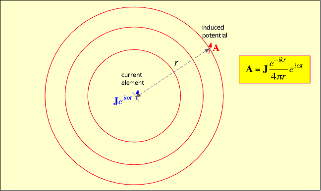
One could write A([2], t) = J([1], t-r/c), but in radio engineering we almost always take everything, including currents, to be harmonic: that is, we assume the current, and the induced potential, have a time dependence like J = cos(ωt), or more generally, taking into account the possibility that phases can change, J = exp(iωt) where the complex exponential is defined as exp(ix) = cos(x) + i sin(x).
For convenient reference here we include a brief discussion of complex exponentials.
Multiplexing
In the real world, many simultaneous transmissions are occurring. An antenna (i.e. at location [2]) doesn't just pick up what you're looking for, but the total potentials due to all currents on its light cone (all the points in the universe from which light would reach the antenna at the time of interest). In order to actually communicate, we somehow have to find the signal we are looking for amongst all the other possible signals. A different way of viewing the same problem is to say that many signals share the same medium: we need to arrange for some kind of multiplexing to allow all these signals to exist simultaneously while still picking out the one we want. There are many methods of multiplexing:
Frequency-division multiplexing: In this approach we look only for signals with a given periodicity and shape. To be more specific, we search only for signals which look very nearly like cos(ωt) (to within a phase shift) for some particular value of the frequency f or ω = 2πf. We can do this because different frequencies of a sinusoidal signal are orthogonal: their product averages to zero.
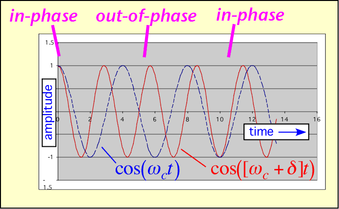
Almost all radio communications depend on frequency-division multiplexing at least partially; government regulations and available technology make this the simplest and most powerful of all methods of sharing the wireless medium. Using filtering, the desired signal can be extracted even when it is much smaller than other interfering signals. (The example shown below is somewhat idealized, but very high rejection of unwanted frequencies can be obtained if the frequencies are well-separated.)

Spatial multiplexing: If my transmitter is farther from your receiver than the realistic range of the signals, then you don't care what I send. We can use the same frequency without interfering with each other. This is the principle behind spatial multiplexing, also known as spatial frequency reuse. On a global scale, the FCC can allow FM radio stations in distant cities to use the same channels (though AM radio can be ducted by the ionosphere and travel across continents, making reuse more difficult). Locally, conventional cellular telephony depends on frequency reuse to allow thousands of subscribers of a single provider to talk simultaneously in a given metropolitan area. Note, however, that some cellular telephony also employs code-division multiplexing, described below. Wireless local area networks (WLANs), which normally operate at very low power and thus fairly short range, are another example of the use of spatial separation to allow frequency reuse, though here there is no central coordination and collisions may occur. Fortunately, WLAN's are not on all the time, leading us to...
Time-division multiplexing: if you listen when I talk, and I extend the same courtesy to you, we can converse even though we use the same airmass to transmit our pressure-wave signals. Similarly, a single frequency and location can be shared without interference by dividing the total time into intervals, and assigning each transmitter to a unique interval. By listening at the correct moment we acquire only the signal of interest, and can ignore other signals in the wireless medium at the same frequency and location. An important limitation is that the range over which such a scheme can be efficiently employed is limited by the propagation velocity of light: you may transmit at the start of your slot, t=t1, but if by the time the signal gets to me at t=t1+r/c =t2 my slot has started, and I will erroneously listen to your signal rather than the one I'm trying to receive.
Direction of arrival: By employing an antenna more sophisticated than a mere slip of wire, I can choose to receive only signals arriving from particular directions and reject the others. (It turns out that such a choice also carries the benefit of collecting more of the received signal, improving sensitivity.) This trick allows users to transmit on the same frequency at the same time to the same location and still be disentangled. However, there are tradeoffs: directional antennas are larger and more expensive than 'isotropic' antennas, and you need to know what direction to point the antenna in. The most common use of such an approach today is to implement long 'point-to-point' connections between two very directional antennas spaced 10-50 km apart; the antenna's directivity is used to capture the tiny signal of the distant transmitter while rejecting other users of the same frequency. Multiple-input multiple-output (MIMO) schemes are conceptually identical to the use of directional antennas, but employ the computational synthesis of multiple virtual directional antennas from a single array.
Code-division multiplexing: A person can hold a conversation with another nearby person in a crowded room with many other conversations taking place simultaneously, as long as the other sounds don't drown the intended speaker out altogether, because our brains can listen for a specific voice in the cacophony. Similarly, we can arrange for a given transmission to be extracted from many simultaneous transmissions on the same frequency band at the same place if we code the desired transmission. A simple method of doing so is to multiply the data we are sending by a specific pseudorandom sequence, which is known to both the transmitter and receiver. For example, let us imagine I wish to send you a (+1). I multiply this data bit by my particular sequence, in this case (1 -1 1 -1 ), and thus send you (1 -1 1 -1 ). At the same time, another user sends a data bit of (-1) using their particular code (1 1 -1 -1 ), so their transmission is (-1 -1 1 1 ). At the receiver, you receive the sum of the two signals: (0 -2 2 0). Multplying this signal by the desired code (1 -1 1 -1) and averaging the result gives (0+2+2+0)/4 = 1, the bit from the desired transmitter. Note that for this trick to work, the different users need codes that are orthogonal or nearly so: that is, two codes multiplied together and averaged (correlated) must yield 0 or at least something small compared to the desired data.
Information and Modulation
In order to send information over a carrier of a given frequency, we must make a change in something: the amplitude, frequency, or phase of the signal. When we do so we inevitably introduce new frequency components into the signal's spectrum. To see why this should be so, we need to think about how we determine how much power a signal has at a given frequency. We multiply the incoming signal by the desired signal, cos(wt), and integrate. The average of the integral over some suitable period is the amount of the signal at the desired (angular) frequency ω.
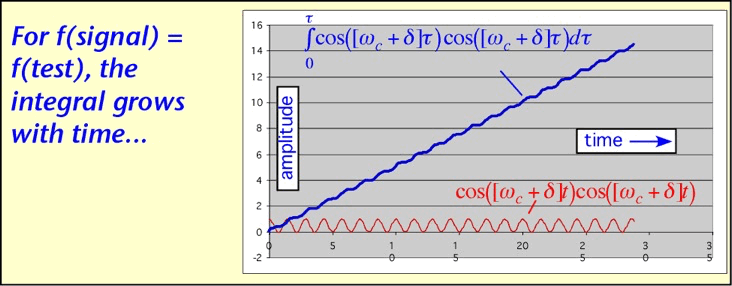
If the signal is a sinusoid with a different frequency from the desired frequency, the integral will oscillate, averaging to zero after a long time (differing frequencies are orthogonal):
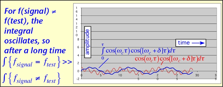
If we start with a simple sinusoid cos(ωt) and modulate it -- for example, change its amplitude slowly -- we will find that the average integral at a different frequency is no longer necessarily 0.
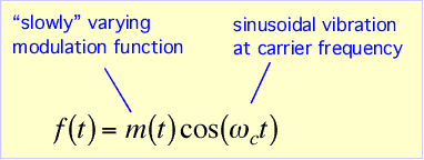
If the test frequency is chosen so that the modulation turns the signal on when e.g. the integrand is positive, and off when the integrand is negative, the contributions will no longer cancel over a long integration time: the modulated signal has acquired a new frequency component corresponding to the sum or difference of the original carrier frequency ω and the frequency of modulation d. (The former is illustrated below.)
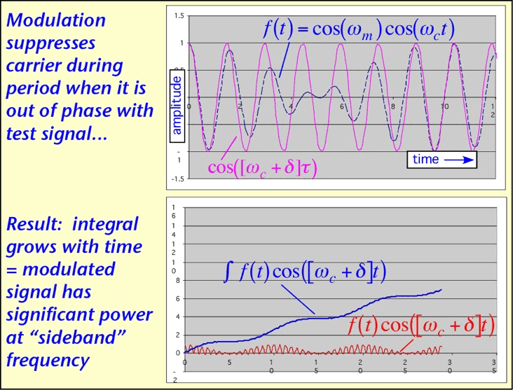
The resulting spectrum has components farther and farther away from the initial carrier frequency when the rapidity of modulation is increased (d is made larger): for a given modulation scheme, higher data rate consumes more bandwidth. It is almost always the case that bandwidth is limited, superficially by regulatory requirements but more fundamentally by the requirement to share with other radio users in the same physical location. More sophisticated modulation schemes can be employed to send more than one bit for each symbol, getting more data from the same bandwidth, but at the cost of reduced immunity to noise.
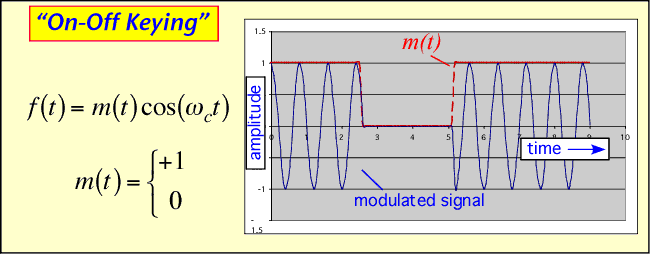
Let's examine a few examples. The simplest possible modulation is the old Morse-code approach of turning the carrier on for a 1 and off for a 0; on-off keying (OOK). Here one bit is transmitted per symbol. This approach is still widely employed in optical fibers but is not often used in wireless communications.
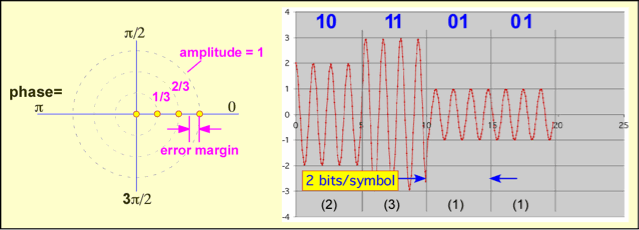
To send more data in the same spectrum we might use multiple values of the amplitude instead of just ON or OFF: amplitude-shift keying (ASK). Note we have depicted the signals here both as amplitude-vs-time and amplitude-and-phase vs. time: the phase plane. The problem with this scheme is that the amount of noise we can tolerate before mistaking e.g. 11 for 10 is obviously less than in the OOK scheme for the same peak power. This is shown as the error margin in the phase plane diagram. Note that here, since we aren't really explicitly keeping track of the phase, the yellow dots could also be shown as circles without changing anything: the error margin is also unchanged, as it is half the distance between two adjacent circles irrespective of the angular location.
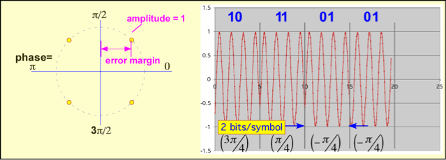
If we are willing to keep track of the RF phase, at the cost of additional complexity we can get a much better noise margin for the same data transmission rate. An example, shown below, is the use of quaternary phase-shift keying, QPSK. We are still able to send two bits for each symbol, but the error margin is much larger than in the equivalent ASK case.
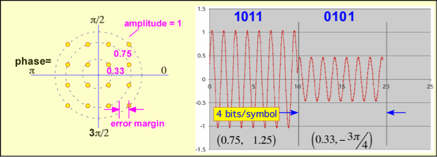
Both phase and amplitude can simultaneously be varied in quadrature amplitude modulation (QAM). More bits can be send in each symbol, but an unavoidable decrease in the tolerance for noise results. Thus, QAM with many possible values works very well in wired channels such as the coaxial cables employed (at least near the customer's site) in digital cable TV, but may have a limited range when employed in a wireless link.
Radio Link Overview
How much noise can we tolerate? The lower limit is set by the thermodynamic fact that at a finite temperature, any degree of freedom of a system with energy levels small compared to (kT) is excited to contain an average energy of kT (where T is the absolute temperature and k is Boltzmann's constant). Thus a resistor of R ohms at room temperature has a mean square voltage between its terminals of 4kTR per Hertz of bandwidth: in radio terms, that's -174 dBm/Hz, where a dBm is a logarithmic measure of power relative to one milliwatt: dBm = 10 log (P/ 1 mW). Real receivers have excess noise as well, measured by their noise figure (also often quoted in dB). Thus, if our signal is modulated at around 1 MHz (a million cycles per second), its bandwidth will be somewhere around 1 MHz and the noise level in the receiver is about (-174 + 10 log (1,000,000) ) = -114 dBm. That's about 4 picoWatts (1 millionth of 1 millionth of a watt), which doesn't seem like much. However, remember that the amount of energy received by the antenna falls off by the square of the distance in empty space, and is likely to be even smaller if people, trees, buildings, cars, and billboards for iPhones get in the way.
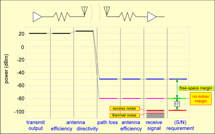
To examine the situation quantitively, we look at the starting signal power at the transmitter and trace its path through the antennas into the receiver. The resulting relationship between signal and noise has to be good enough to support whatever modulation we chose to try to use. An example of such a calculation is shown below. The transmitted power is used effectively by having the transmitting antenna 'point' at the receiving antenna (the directivity of the antenna), but is decreased dramatically by the path loss: the path loss in blue corresponds to free space, while than in purple depicts the extra loss one might encounter indoors where obstacles block and attenuate the signal. Meanwhile, the thermal noise and the excess noise of the receiver raise the noise floor. The ratio between the signal and noise, 17 dB in this example for the 'indoor' path, represents the accuracy with which the receiver can determine the amplitude and phase of the received signal, and thus the number of bits that could be sent per symbol before errors in determining which symbol was transmitted become likely.
For a more detailed discussion of these topics, see Dan's (now somewhat dated) book, RF Engineering for Wireless Networks, Elsevier 2004.
